| Power input | Input voltage (V) & frequency (Hz) | 3-phase AC 380-480VAC, 50/60Hz |
| Allowable voltage range (V) | Voltage fluctuate range: ±10% |
| Voltage unbalance rate: <3% |
| Frequency fluctuation:≤±5% |
| Power output | Output voltage (V) | 3-phase 0-rated input Voltage |
| Output power (KW) | 0.75-2.2KW |
| Output frequency (Hz) | Vector control: 0-300Hz; V/F control: 0-320Hz |
| Control features | Carrier Frequency | 0.5-16KHz. The carrier frequency can be automatically adjusted according to the load characteristics. |
| Frequency resolution | Digital setting: 0.01Hz; Analog setting: maximum frequency × 0.025% |
| Control Methods | Closed loop control (FVC), open loop control (SVC), V/F control, V/F separation control |
| Overload Capacity | Type G:150% rated currenty 60 seconds, 180% rated current 3 seconds |
| Type P:120% rated currenty 60 seconds, 150% rated current 3 seconds |
| Starting Torque | Type G: 0.5Hz/150% (SVC); 0Hz/180% (FVC) |
| Type P: 0.5Hz/100% |
| Speed range | 1:100 (SVC); 1:1000 (FVC) |
| Steady Speed Accuracy | ±0.5% (SVC); ±0.02% (FVC) |
| Torque control Accuracy | ±5%(FVC) |
| Torque Boost | Automatic torque boost, automatically boost torque according to output current |
| Manual torque boost 0.1%-30.0% |
| V/F curve | Linear type |
| Multi-point type |
| N-th power V/F curve (1.2th power, 1.4th power, 1.6th power, 1.8th power, 2th power) |
| V/F Separation | 2 ways: full separation, half separation |
| Acceleration and deceleration curve | Linear or S-curve acceleration and deceleration.
Four kinds of acceleration and deceleration time, the acceleration and deceleration time range is 0.0~6500.0s |
| Jog control | Jog frequency range: 0.00-50.00Hz |
| Jog acceleration and deceleration time: 0.0-6500.0s |
| DC Braking | DC braking frequency: 0.00Hz-maximum frequency |
| Braking time: 0.0s-36.0s |
| Braking action current value: 0.0%-100.0% |
| Simple PLC, multi-speed operation | Realize up to 16-speed operation through built-in PLC or control terminals |
| Automatic voltage regulator(AVR) | When the grid voltage changes, it can automatically keep the output voltage constant |
| Built-in PID | Conveniently form a closed-loop control system, suitable for process control such as pressure control and flow control |
| Over-voltage over-current stall control | Automatically limit current and voltage during operaion to prevent frequent over-current and over-voltage tripping |
| Fast current limiting function | Minimize over-current faults and protect the normal operation of the inverter |
| Torque limit and control | Excavator" feature, automatically limit the torque during operation to prevent frequent over-current tripping; closed-loop vector mode can realize torque control |
| Special features | Outstanding Performance | Asynchronous and synchronous motor control with high-performance current vector control technology |
| Momentary Stop | In the event of an instantaneous power failure, the voltage reduction is compensated by the load feedback energy, and the inverter continues to run for a short time |
| Rapid Current Limit | Avoid frequent over-current faults of the inverter |
| Timing control | Timing control function: set time range from 0.0-6500.0 minutes |
| Multi-motor Switching | Four sets of motor parameters, which can realize four motor switching control |
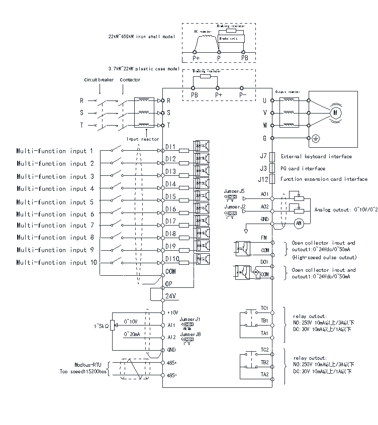
| Bus Support | Fieldbus support: Modbus |
| Multi-encoder support | Differential, open collector, resolver encoders are supported |
| Motor overheat protection | Analog input AI3 can accept motor temperature sensor input (PT100, PT1000) |
| Operation features | Command source | Operation panel, control terminal, serial communication port,
can be switched in a variety of ways |
| frequency source | Multiple frequency sources: digital, analog voltage, analog current, pulse, serial port, canbe switched in a variety of ways |
| Auxiliary frequency source | 10 auxiliary frequency sources. Auxiliary frequency fine-tuning and frequency synthesis can be flexibly realized |
| Input terminal | Standard:
5 digital input terminals, one of which supports high-speed pulse input up to 100kHz
2 analog input terminals, 1 only supports 0-10V voltage input, 1 support 0 ~ 10V voltage input or 4-20mA current input
The CF40A control board has 5 more digital input terminals for voltage input, and supports PT100/PT1000 |
| Output terminal | Standard:
1 high-speed pulse output terminal (optional open collector type), support 0-100kHz square wave signal output
1 digital output terminal
1 relay output terminal
1 analog output terminal, support 0-20mA current output or 0-10V voltage output
CF40A control board:
2 digital output terminals
2 relay output terminals
2 analog output terminals, support 0-20mA current output or 0-10V voltage output |
| Interface | LED display | Real-time display of the inverter's operating status, monitoring parameters, function parameters, fault codes and other information |
| Key lock and function selection | Part or all of the keys can be locked, and the scope of action of some keys can be defined to prevent misoperation |
| Protective Function | Power-on motor short circuit detection, input and output phase loss protection, over-current protection, over-voltage protection, under-voltage protection, overheat protection, overload protection, etc. |
| Optional accessories | Differential input PG card, OC input PG card, resolver PG card |
| Environment | Place of use | Indoor, no direct sunlight, no dust, corrosive gas, flammable gas, oil mist, water vapor, dripping water or salt, etc. |
| Altitude | Below 1000m |
| Ambient Temperature | -10℃-+40℃ (Ambient temperature is 40℃-50℃, please use with derating) |
| Humidity | Less than 95%RH, no condensation |
| Vibration | Less than 5.9m/s2 (0.6g) |
| Storage Temperature | -20℃~+60℃ |
| IP Level | IP20 |
| Pollution level | PD2 |
| Distribution System | TN , TT |